E-Mail:ttpump@163.com
Phone:+86-13615332800
Tel:+86-0533-4160533
Address:3 Yanhe East Road, Boshan, Zibo, Shandong

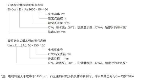
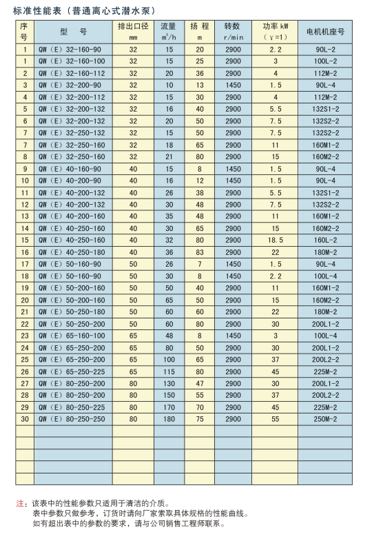
The QW submersible pump is a single-stage, single suction submersible centrifugal pump.
The product standards are CJ/T3038-1995 "Submersible Sewage Pump" and JB/T8857-2000 "Centrifugal Submersible Sewage Pump".
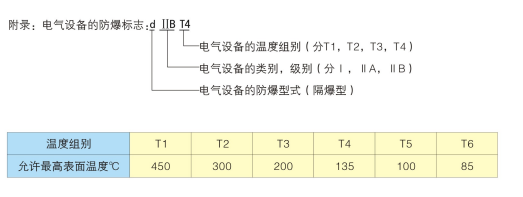
QWE is a flameproof submersible pump. The design and manufacturing of submersible motors shall comply with GB3836.1-83 "General Requirements for Explosion proof Electrical Equipment for Explosive Environments" and GB3836.2-83 "Explosion proof Electrical Equipment for Explosive Environments - Explosion proof Electrical Equipment" d ".
The QW (E) submersible pump can be manufactured using different materials according to different medium conditions.
The QW (E) submersible pump can be used for submersible transportation up to 20m underwater,
For depths exceeding 20m, please contact our product design department.
QW submersible pumps are mainly used in industries such as sewage treatment, petroleum, chemical, mining, papermaking, food, refineries, power plants, metallurgy, etc. for discharging wastewater, sewage, and various corrosive and abrasive organic and inorganic compounds. QWE explosion-proof submersible pump is mainly used in environments prone to natural and explosive hazards.
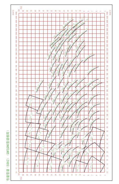
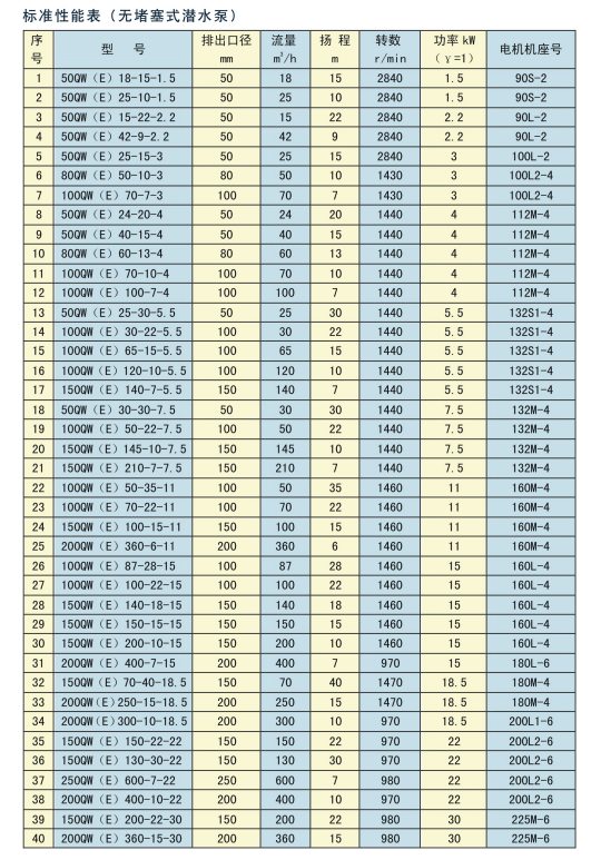
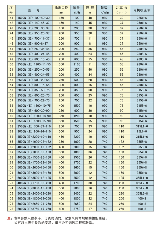
Caliber:DN 25-600mm
Flow rate:Q 10-3750m³/h
Head:H 5-80m
Power:N1.5-250Kw
Temperature:T ~60℃
Pressure:P ~1.6MPa

Design of hydraulic components: The QW (E) submersible pump adopts an unobstructed flow channel design for the flow passage component with a turn meter; In some cases, the introduction of advanced centrifugal pump hydraulic models from abroad may not be suitable for situations with high impurities in the pump operation. The characteristics of imported foreign hydraulic models are high efficiency, energy saving, and good balance.
The design of an unobstructed hydraulic model increases the width of the flow surface of the impeller and pump body, ensuring the smooth passage of pollutants and avoiding possible blockage and entanglement caused by water flow at low speeds. This uniquely designed impeller channel, combined with a reasonable vortex chamber, allows liquids containing large amounts of dirt to pass through smoothly. The impeller is designed with dual channels to avoid the imbalance of a single channel impeller. In addition, the impeller has undergone dynamic and static balance tests, ensuring that the pump does not vibrate during both no-load and loaded operation.
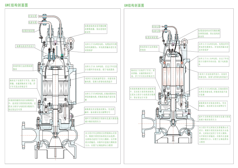
Design of the complete pump structure: The QW (E) submersible pump consists of two parts: the motor and the pump, separated by an isolation chamber and mechanical seal components.
Design of shaft seal: The impeller design is equipped with secondary blades to prevent high-pressure water from entering the sealing chamber, thus providing good sealing protection for the submersible motor. The seal is a double end mechanical seal, which is lubricated and isolated by a certain amount of lubricating oil in the isolation chamber.
Design of motor: The motor is a dry-type motor, with a Y-series motor design for the rotor and stator. It has a slender body, F-class insulation, IPX8 protection level, and is equipped with a thermal overload protector to ensure safe and stable operation of the motor. Install bearing temperature rise monitoring for motors with a power of over 37 kW. Pumps with a power of 18.5kW or more are equipped with a self circulating cooling system. The impeller blades allow the water inside the pump to enter the outer periphery of the stator chamber for ring cooling, ensuring the normal operation of the pump at the lowest water level in the pit. The normal operating environment temperature of the submersible pump does not exceed 60 ℃. The highest explosion-proof level of the motor is designed as dlIBT4.
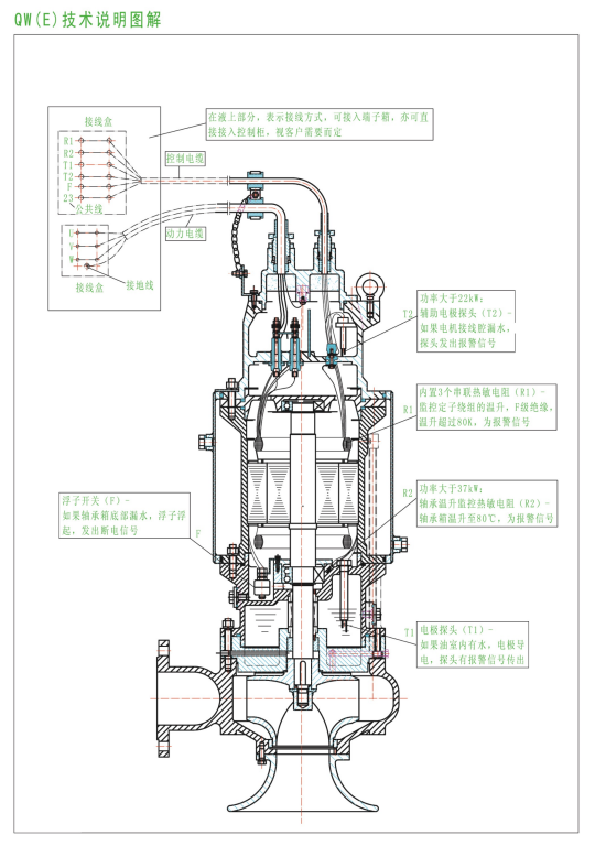
Design of the control section: An oil-water probe is installed in the oil isolation chamber. When the mechanical seal on the pump side is damaged, water enters the oil isolation chamber, and the probe sends a signal to the home. The control system displays an alarm to prompt maintenance; The lower end of the motor is equipped with a float switch. When the mechanical seal on the motor side is damaged, water enters the motor chamber and the float rises. The control system will display an alarm and the pump will be powered off for protection. It can automatically control the water level according to user requirements, and is equipped with automatic protection devices and control cabinets, ensuring safe and reliable pump operation.
The QW (E) dedicated control cabinet has the function of fully automatic protection for submersible pumps (overheating, overload, phase loss, short circuit, leakage, etc.). The method of pump monitoring is briefly described as follows:
The monitoring of motor temperature rise is represented by a thermistor installed in the stator. When the temperature exceeds the allowable value, the over temperature signal light will display and the electrical system will activate (alarm or power off, depending on the design); The humidity of the motor is reflected by measuring the insulation resistance. When the insulation resistance is lower than a specific value (according to relevant standards), a short-circuit signal light will be displayed; Mechanical seal leakage will be displayed in the leakage signal light. All protection and monitoring of the motor are implemented by the control cabinet. For the control part, please refer to the "QW (E) Technical Explanation Diagram".
If the user is equipped with their own control cabinet or control system, in addition to monitoring for overload, phase loss, short circuit, etc., other parts of the motor should also be controlled and monitored according to the "QW (E) Technical Explanation Diagram".
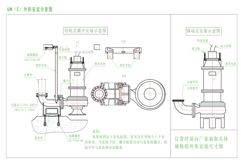
The installation methods of the △ pump include mobile (below 7.5kW) and rail coupling installation. When the guide rail coupling is installed, the coupling device automatically couples with the coupling base when the pump is lowered, and automatically detaches from the coupling base when lifted, making installation and maintenance convenient.
For highly corrosive media, please provide detailed composition and content to facilitate the correct selection of pump and cable materials.
(2) The flow rate and head of the pump. It should be noted that the performance spectrum and parameters in the sample are for reference only. After making a preliminary selection based on the spectrum, please request the performance curve of the specific pump specifications from our company for final selection, or have our sales engineer personally select the specific pump model for you.
(3) The installation method of the pump (mobile installation or rail coupling installation, mobile installation is limited to below 7.5kW). Users can request specific pump specifications and installation dimension drawings from our company. Our company's standard design for submersible pumps is a guide rail installation, with the height of the guide rail configured according to user requirements.
(4) If there are no special requirements for the monitoring of the motor, our company will configure it according to the standard design, as shown in the "QW (E) Technical Explanation Diagram".
(5) Requirements for explosion-proof rating of motors.
(6) Requirements for electrical systems, such as the need for liquid level control switches? Do you need a terminal box? What are the technical requirements for the control cabinet? The attached equipment is required to be explosion-proof and its explosion-proof level.
Our company's submersible pump is configured normally, with a cable length of 10m. Please note that if the control cabinet is located in a non explosion proof area, do not forget to check if the cable length is sufficient.
Tel
+86-0533-4160533
E-mail:ttpump@163.com
Fax:+86-0533-4162286
TelPhone:+86-0533-4160533
Address:3 Yanhe East Road, Boshan, Zibo, Shandong

Copyright © 2024 ZIBO BOSHAN TIAN TI CACUUM CO.,LTD 备案号:鲁ICP备2020049334号
 鲁公网安备 37030402001448号